Now you've met the brain and the muscle of the motherboard, now it's time to wire things up.
In Part 1, we covered the beefy components like the CPU socket, RAM slots, and PCIE lanes. But even the most powerful parts won't work without proper power, storage and connections.
In this post, we will be diving into the unsung heroes of the motherboard-theb power connectors, SATA ports fan headers, and those tiny front panel pins that's trippping even for experienced buiders. Understanding these pieces is essential.
Let's plug in andf power up!
Power Connectors
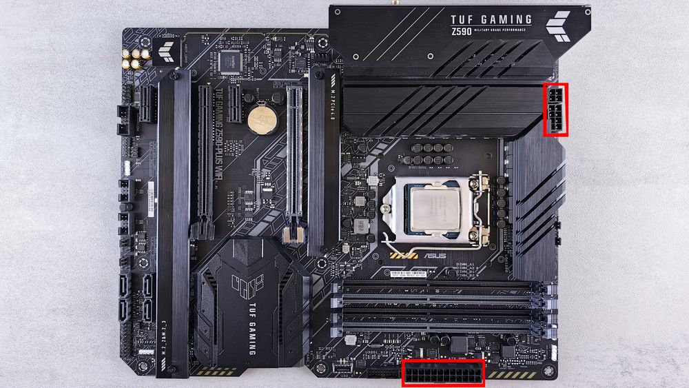
To power up your system, plug in: 24-pin ATX (Main System Power) and 8-pin EPS (CPU power).
Tips: Some high-end boards have dual 8-pin CPU connectors—for stable overclocking and power delivery.
Rear I/O Panel – External Connectivity
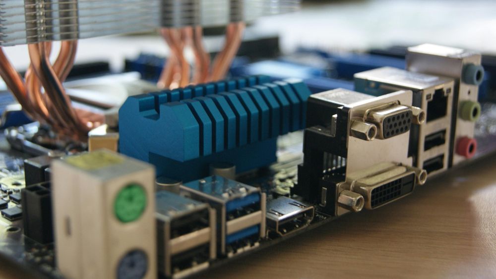
The metal plate (some have back plates integrated on the board itself) on the back of your motherboard includes:
USB ports (2.0, 3.0, 3.2, Type-C)
Audio jacks
Ethernet port
Display outputs (HDMI, DisplayPort) – only work if your CPU has integrated graphics
Higher-end boards may include Wi-Fi antennas and BIOS flashback buttons.
Front Panel Connectors – Small but Important
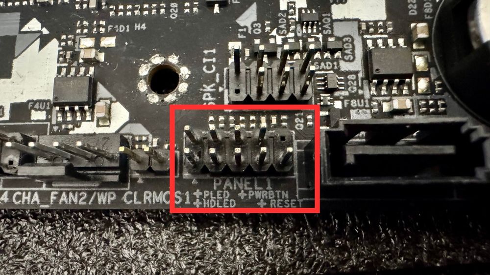
Tiny pins usually labeled F_PANEL (PANEL1 for this reference photo). These are the pinout that you will be connecting to the front I/O (The cables that connects to the power button from the case you bought.
You’ll connect:
Power switch
Reset switch
HDD LED
Power LED
Beware: These are tricky—consult the manual.
Cooling Connectors – Absolutely Required
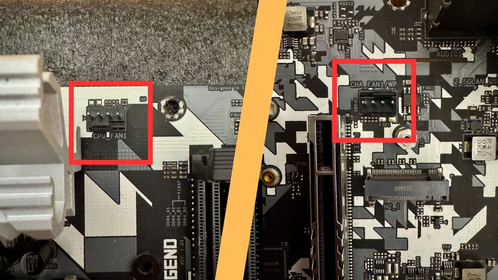
These are the pinouts for your CPU cooler and case fans.
The CPU_FAN is for the CPU cooler fan.
The CHA_FAN (Chassis fan) is where your case fans connects.
Tips: If you got a water cooler, you can connect the water pump to either of these pinout as well, just make sure to set the speed to 100% in the BIOS settings in order to get the optimal performance.
In some motherboards, there will be a specific pinout for the water pump as well (labeled as AIO_PUMP or PUMP_HEADER).
Audio and USB – The Coup De Grace
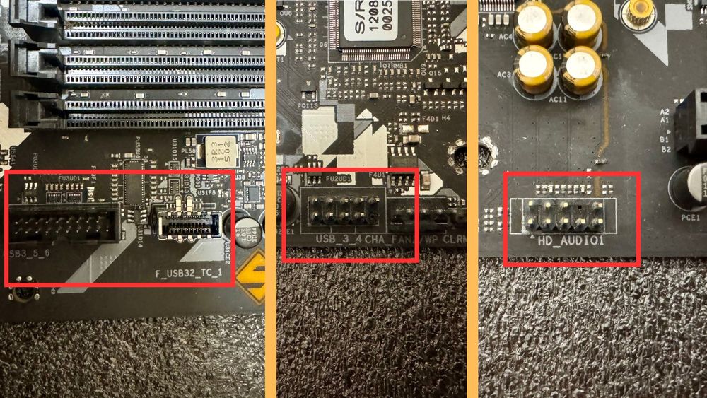
Last but not least, let's don't forget the critical part of a PC, the USB and Audio ports.
These are the pinout that you will be connecting to the front I/O (The cables that connects to the USB and Audio port from the case you bought). The one with the 19 pin (Left side on the photo) is for USB 3.0 port of the front I/O, and next to it is the USB Type-C port. USB 2.0 is the 9 pin connector with the bottom right pin missing.
For the audio (Labeled as AC97 or HD_Audio) is another 9 pin but with a missing pin on the second top right counting from the right side. It may sounds mouthful but worry not, all of the pinout are absolutely fool-proof.
Final Thoughts
Learning how to “read” a motherboard makes every step of PC building easier—from choosing parts to troubleshooting. Bookmark this guide and come back to it when you’re ready to build, upgrade, or explore.
And don’t forget—choosing a good case like one from our darkFlash case collection helps showcase your build and makes cable management much smoother!